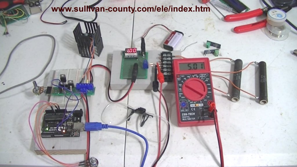
Fig. 1 Test setup Arduino controlled constant current source.
Review Ohm's Law for Trouble-Shooting Constant Current Source
by Lewis Loflin
This is a short review of Ohm's Law as it relates constant current sources and series-parallel circuits.
Note: click on any image for larger view.
Fig. 1 is the test setup for a series of articles related to circuit analysis. I assume one has a basic knowledge of Ohm's Law and DC power supplies.
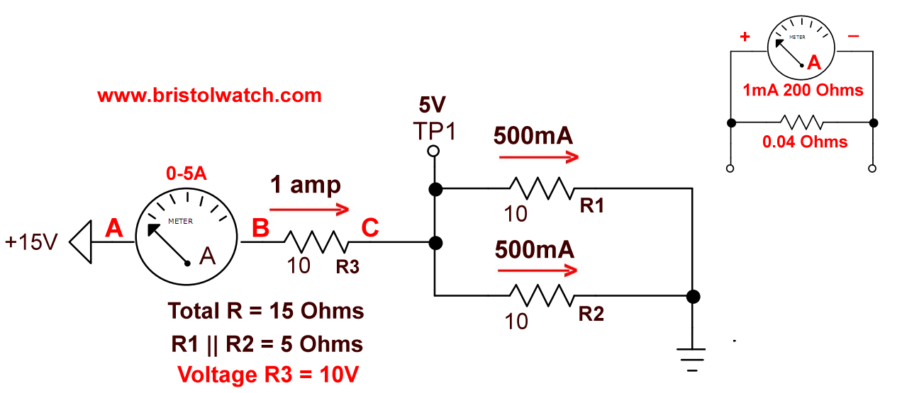
Fig. 2 series-parallel circuit with three 10 Ohm resistors.
Fig.2 illustrates a basic series-parallel circuit with resistors. For simplicity I used three 10-Ohm resistors.
The amp meter is in series with R3 both are in series with the parallel combination of R1, R2. that together form a 5-Ohm resistor.
Let's note some properties of series-parallel circuits:
In a series circuit current is the same through all elements. The current through R3 equals the current through R1 || R2.
Total resistance is the sum of the individual resistances. Thus R3 = 10-ohms and R1/R2 = 5-ohms for a total of 15-ohms.
The current is 15-volts divided by 15-ohms equal 1 amp.
In a series circuit voltage divides based on the resistance values of each element. The sum of the voltage drops equals the input voltage.
Voltage drop across R3 is 10-ohms X 1 amp = 10-volts. The drop across the 5-ohm combination of R1/R2 is 5-ohms X 1 amp = 5-volts. 5-volts + 10-volts = 15-volts.
In a series circuit power divides based on individual voltage drops. The sum of power in each element adds back to total input power.
With R3 10-volts X 1 amp = 10-watts. With R1/R2 at 5-ohms 5-volts X 1 amp = 5-watts. Total power with all three resistors is 15-watts. 15-volts input X 1 amp = 15-watts.
Note the ammeter depicted in the upper right hand corner. This is a very low resistance device. It presents very little voltage drop and is ignored in these calculations.
Note: ammeters are ALWAYS used in series and never in parallel!
In a parallel circuit such as R1/R2 the voltage across each element is equal. The current will divide based on individual resistance, but add back to total current.
In this case R1 and R2 both equal 10-ohms and the current will divide equally. Going by resistance formula 1 / ( ( 1 / 10 ) + ( 1 / 10) ) = 1 / 0.2 = 5-ohms.
For R1 5-volts / 10-ohms = 500mA. For R2 5-volts / 10-ohms = 500mA. Both add back to 1 amp. Power as current X volts for both produce 2.5 watts of heat. Adds back to 5-watts.
Whew, got that out of the way.
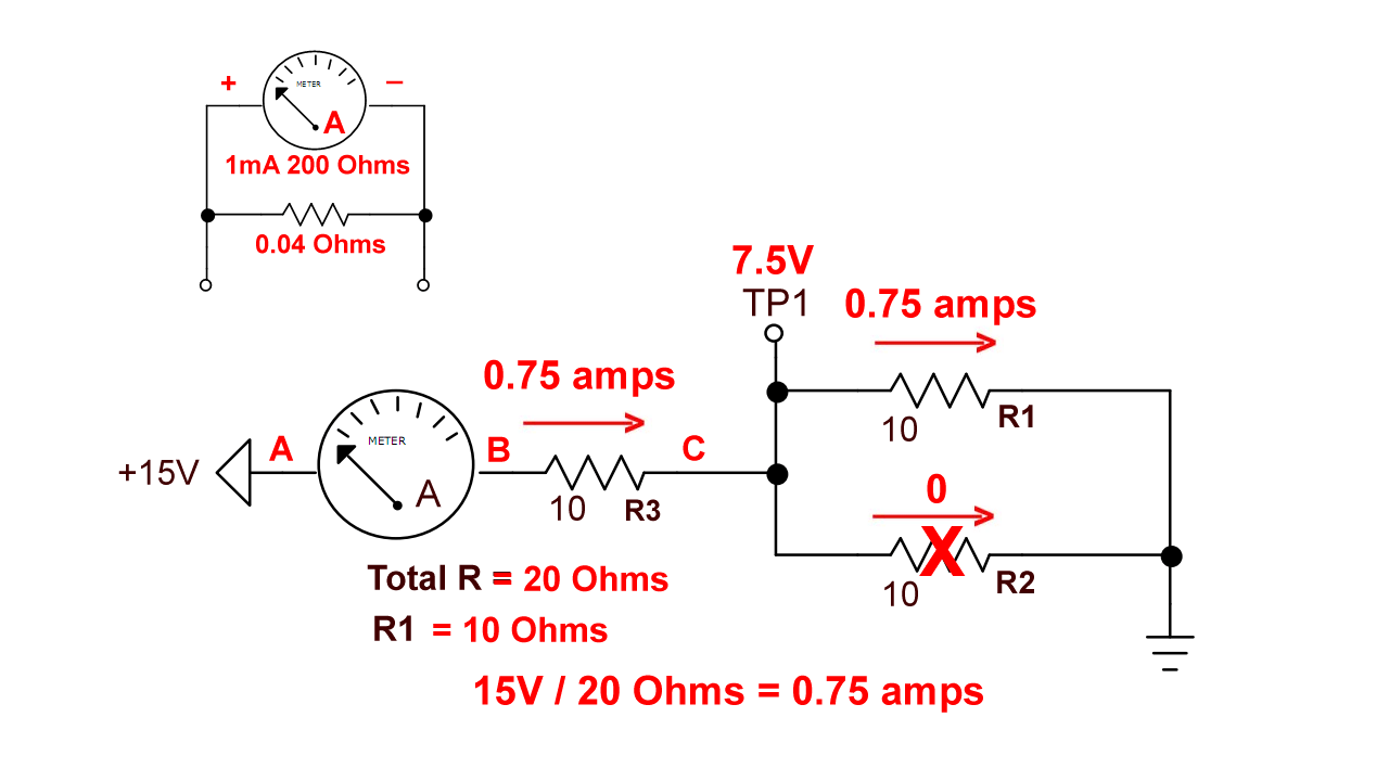
Fig. 3 Series-parallel circuit with three 10 Ohm resistors, one resistor open.
In Fig. 3 one of the parallel 10-ohm resistors has failed producing a circuit with two 10-ohm resistors in series.
The current through both resistors is the same, the voltage drop across each and power is equal, but the total resistance has changed to 20-ohms.
15-volts divided by 20-ohms = 750mA. The voltage drops are now 7.5-volts across each resistor. Power in each resistor is 7.5-volts X 750mA = 5.625 watts. Multiply by two equals 11.25 watts.
Multiply 15-volts input X 750mA = 11.25 watts.
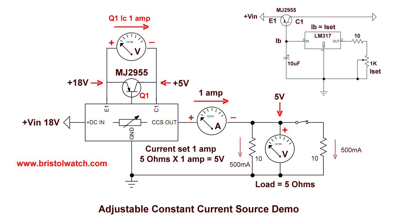
Fig. 4 Series-parallel circuit connected to constant current source.
What is a constant current source? One web definition:
A constant current source is a power source which provides a constant current to a load, even despite changes and variance in load resistance.
In Fig. 4 I have connected a constant current source to our three series-parallel resistors. The power input is 18-volts.
Unlike Fig. three when the total resistance changed and change the current, open either R1 or R2 will not change the current from 1 amp I set it for.
The 5-ohm parallel combination will become 10-ohms, but the fixed 1 amp will produce 10-volts on the remaining resistor. The voltage drop will change but not the current.
See Constant Current Source Theory Testing
Date: 7-11-2021
- Constant Current Source Theory Testing
- Arduino Measures Current from Constant Current Source
- Review Ohm's Law for Trouble-Shooting CCS Circuits
- Arduino Power Magnetic Driver Board for Stepper Motors
- Arduino Controlled Power Constant Current Source
Related video to above:
- Constant Current Source Multimeter Trouble Shooting
- Ohm's Law Review for Constant Current Source
- Arduino Unipolar Stepper Motor Driver Board with Arduino Code
- Arduino Controlled Constant Current Source
- Related to above:
- Using a Unipolar Stepper Motor with a Arduino
- ULN2003A Darlington Transistor Array with Circuit Examples
- Tutorial Using TIP120 and TIP125 Power Darlington Transistors
- YouTube
- ULN2003A Transistor Array with Arduino
- Arduino Stepper Motor Control
- Using the TIP120 & TIP125 Darlington Transistors with Arduino
- Constant Current Circuits with LM317, LM334, etc.
- Experiments with TL431 Shunt Regulator
- TL431 Precision Current Regulator Circuits
- TL431 Based Current Limiter Constant Current Source Circuits
- TL431 Shunt Regulator Circuits
- Simple Triac-SCR Test Lab for You Tube
- Constant Current Circuits with the LM334
- LM334 CCS Circuits with Thermistors, Photocells
- LM317 High Power Constant Current Source Circuit
- LM317 Constant Current Source Circuits
- LM317 Adjustable Voltage Source Current Boost
- LM317 Constant Current Source for Lighting LEDs
- 3 Amp LM741 Op-Amp Constant Current Source
- Comparator Circuits:
- Comparator Theory Circuits Tutorial
- Comparator Hysteresis and Schmitt Triggers
- Voltage Comparator Information And Circuits
- Looking at Window Comparator Circuits
- Opto-Coupler SCR and Triac Circuits:
- Improved AC Zero Crossing Detectors for Arduino
- Zero-Crossing Detectors Circuits and Applications
- Basic Triacs and SCRs
- Solid State AC Relays with Triacs
- Light Activated Silicon Controlled Rectifier (LASCR)
- Light Activated SCR Based Optocouplers Circuit Examples
- Comparing Photo Triac, Photo SCR Opto-Couplers
- Silicon Controlled Rectifier Review and Circuits
- Silicon Controlled Rectifiers Connected as Power Triacs