List of Electronic Projects by Lewis Loflin
I've been a part-time adjunct professor at a local community college teaching electricity and electronics. My electronics website reflects what I've taught or been asked to look into by visitors. I have 40 years experience in electronics from vacuum tubes to modern solid state and industrial controls. In college I had a year each of physics, chemistry, and biology along with C, C++. Pascal, and assembly.
I taught myself the coding for Arduino, PICAXE, Raspberry Pi, Microchip PIC, Debian and Slackware Linux, CSS etc which I approach in a way to give my students a basis for their own projects. Every page on this website was hand-coded by me. My education philosophy is learn the basics, find working examples, then use what works as a foundation for further learning. Modify and try new ideas. I'd say my job title would be applied technologist.
New for 2021
Date: 7-11-2021
In the process of publishing new gadgets and circuit ideas. Plus new tutorials and videos. They will be published here on this site.
- List of Electronic Projects by Lewis Loflin
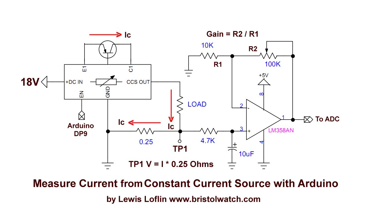
- Arduino Measures Current from Constant Current Source
- Constant Current Source Theory Testing
- Review Ohm's Law for Trouble-Shooting CCS Circuits
- Arduino Power Magnetic Driver Board for Stepper Motors
- Arduino Controlled Power Constant Current Source
- Theory and Operation of Capacitors
Related video to above:
- Constant Current Source Multimeter Trouble Shooting
- Ohm's Law Review for Constant Current Source
- Arduino Unipolar Stepper Motor Driver Board with Arduino Code
- Arduino Controlled Constant Current Source
- Related to above:
- Using a Unipolar Stepper Motor with a Arduino
- ULN2003A Darlington Transistor Array with Circuit Examples
- Tutorial Using TIP120 and TIP125 Power Darlington Transistors
- YouTube
- ULN2003A Transistor Array with Arduino
- Arduino Stepper Motor Control
- Using the TIP120 & TIP125 Darlington Transistors with Arduino
Other Circuits
- Hall Effect Magnetic Switches and Sensors
- Transistor-Zener Diode Regulator Circuits
- Build an Adjustable 0-34 volt power supply with the LM317
- Coils for Highly Selective Crystal Radio
- Neon (NE-2) Circuits You Can Build
- Understanding Xenon Flashtubes and Circuits
- Arduino
- Arduino PWM to Analog Conversion
- Arduino Analog Digital Conversion Voltmeter
- Better Arduino Rotary Encoder Sensor
- Simple 3-Wire MAX6675 Thermocouple ADC Arduino Interface
- YouTube:
- 3-Wire MAX6675 Thermocouple ADC Arduino Interface
- Opto-Coupler SCR and Triac Circuits:
- Improved AC Zero Crossing Detectors for Arduino
- Zero-Crossing Detectors Circuits and Applications
- Simple Triac-SCR Test Lab
- Light Activated SCR Based Optocouplers Circuit Examples
- Comparing Photo Triac, Photo SCR Opto-Couplers
- Silicon Controlled Rectifier Review and Circuits
- Silicon Controlled Rectifiers Connected as Power Triacs
- Using Zero-Crossing Detectors with Arduino
- Hardware Interrupts Demo and Tutorial for Arduino
- In Depth Look at AC Power Control with Arduino
- Micro-controller AC Power Control Using Interrupts
- Light Activated SCR Based Optocouplers Circuit Examples
- Solid State AC Relays with Triacs
- YouTube
- Zero-Crossing Detectors Circuits and Applications
- Zero-Crossing Circuits for AC Power Control
- In Depth Look at AC Power Control with Arduino
- Micro-controller AC Power Control Using Interrupts
- YouTube Video for Arduino AC Power Control